- 01Model the featureThe real feature, at nominal size, in the real orientation.
- 02Print a stepped couponSeveral clearances on one part, same material, same machine.
- 03Test the fitFind the step that behaves the way you need: sliding, or pressed.
- 04Take that numberIt is true for your setup, which is the only place it has to be true.
- 05Apply and printUse it in the real model. Re-run the coupon when the material changes.
Free download · OpenSCAD source
Stepped fit-test coupon
Parametric source, not a mesh, so you can set the nominal size and the step to your own part. We have not test-printed it, and this site does not publish measurements it did not take.
Download the sourceMeasure the same feature three times
A single reading tells you almost nothing. Layer lines, seam placement and slight elephant-foot at the base all shift a measurement depending on exactly where the jaws land. Take three readings along a feature and use the spread, not the average, to judge whether the part is usable.
If the three readings differ by more than about 0.1mm, the problem is the print rather than the measurement, and the usual causes are an unlevelled first layer, over-extrusion, or the part shifting slightly during printing.
Holes come out undersized. Always.
A circular hole printed on its side is approximated by straight line segments, and those segments cut inside the true circle. The practical result is that a hole prints smaller than nominal, typically by 0.1 to 0.4mm depending on diameter, layer height and nozzle size.
This is geometry, not calibration, so it does not go away when the printer is dialled in. Either oversize holes in CAD, or plan to drill or ream them afterwards. For anything that has to accept a bearing or a bolt, drilling to size is faster and more repeatable than tuning.
How much clearance to design in
There is no universal clearance number, and any site that gives you one is guessing on your behalf. The figure depends on your printer, the material, the print orientation, how well extrusion is calibrated and the geometry itself, and those vary more between two machines than the number would suggest.
What does transfer is the method. Print a test coupon with the same feature at several clearances, on the same machine, in the same material and orientation as the real part. A stepped fit-test print takes twenty minutes and gives you a number that is true for your setup rather than for somebody else's.
As a starting point for that test rather than as an answer: a sliding fit generally needs noticeably more clearance than people expect, and a press fit needs less material removed than a printed hole already loses to segmentation. Start the coupon around a couple of tenths of a millimetre either side of nominal and bracket from there.
The coupon, if you would rather model it yourself
The geometry is deliberately trivial, and you do not need our file to build it. A flat plate, a row of holes around your nominal size, each one a fixed step larger than the last, and a number beside each hole saying how far above nominal it sits.
Six holes at 0.10mm steps covers the range most fits land in. Make the plate a little thinner than the hardware you are testing, so a bolt or a rod seats all the way through, and leave about 4mm of material around each hole so a thin wall is not what fails.
Print it flat, in the real material, at the settings you will use for the real part. A coupon printed in PLA tells you very little about a PETG fit, and one printed on its side tells you very little about a hole printed flat.
What calipers actually need to do
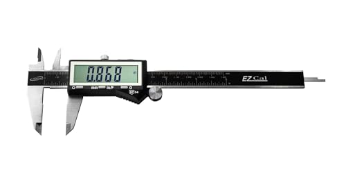
Any digital caliper reading to 0.01mm is enough for printed parts. The precision is not the limiting factor; the print is. What matters more is that the jaws are flat and the zero holds when you close them, because a caliper that drifts makes every reading a guess.
Do not treat a workshop caliper as metrology. It is repeatable enough to tell you whether a part will fit, which is the question you actually have.